Diaphragm |
  
|
Diaphragm |
|
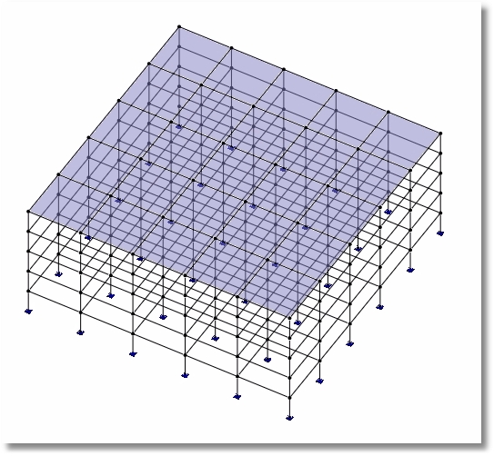
Diaphragms are a way to specify that a group of coplanar nodes must translate and rotate as though they were connected by a rigid plate.
There are at least two different ways to define diaphragms: Graphically and in tabular format.
Graphical Method
If you click Draw > Draw Diaphragms, it will display the Diaphragms dialog. Note that it offers Generic and Regular diaphragms.
Generic diaphragms can be in any orientation, including sloping planes. They are defined by clicking on four nodes that define the perimeter of the area that is to be considered a diaphragm.
Regular diaphragms must be defined as falling in the XZ, YZ, or XY plane. They are defined by selecting a plane and one or more nodes. If more than one node is selected, the program will automatically create as many unique diaphragms as there are nodes selected.
Tabular Method
Click Tables > Diaphragms Data to open the Diaphragms table. This allows existing diaphragms to be edited or deleted, and allows new diaphragms to be defined.
The type can be set to Generic, XZ Plane, YZ Plane, or XY Plane. If the type is set to Generic, then four unique nodes must be entered in the four remaining columns in the table. If the type is set to one of the other options, then only one node number is required, and the same number should be entered into all four columns in the table.
