Steel Design Results |
  
|
Steel Design Results |
|
Click Steel Design > Steel Design Results to open the Steel Design Results table.
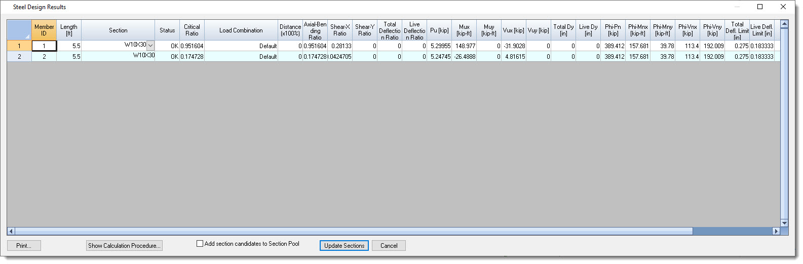
This table presents the results of the most recent Steel Design process. Each line represents a member in the model and presents the following data:
Member ID: The ID of the member.
Length: The actual member length, not the unbraced length for flexure or for Euler buckling.
Section: The AISC section for which design results are displayed.
Tip: Click the dropdown arrow in the Section cell to view a list of other sections selected by the Steel Design routine subject to the limitations of the Section Prefix and the Section Pool.
Tip: Selecting a different section will invalidate the analysis results due to changes in stiffness. So be sure to reanalyze the model and rerun the Steel Design after making any section changes.
Status: Indicates an OK or NG status to show whether the selected member satisfies code requirements or not.
Critical Ratio: Reports the highest ratio found after running all of the required steel code checks on the member considering Axial & Bending, Shear, and Deflection.
Load Combination: Indicates the Load Combination responsible for producing the Critical Ratio.
Distance: Reports the location where the critical design was found to occur. 0 indicates that the critical design location was at the starting end of the member. 1 indicates that the critical design location was at the ending end of the member. A decimal indicates a location somewhere in between starting and ending end.
Axial-Bending Ratio: Indicates the highest ratio that occurred on the member due to combined axial and flexural design when subjected to the load combination that produced the Critical Ratio.
Shear-X Ratio: Indicates the highest ratio that occurred on the member due to strong direction shear when subjected to the load combination that produced the Critical Ratio.
Shear-Y Ratio: Indicates the highest ratio that occurred on the member due to weak direction shear when subjected to the load combination that produced the Critical Ratio.
Total Deflection Ratio: Calculated as controlling Total Load Deflection/(Span/Total Load Deflection Denominator) when subjected to the load combination that produced the Critical Ratio.
Live Deflection Ratio: Calculated as controlling Live Load Deflection/(Span/Live Load Deflection Denominator) when subjected to the load combination that produced the Critical Ratio.
Pu: Axial load at the controlling distance when subjected to the load combination that produced the Critical Ratio.
Mux: Moment about the strong axis at the controlling distance when subjected to the load combination that produced the Critical Ratio.
Muy: Moment about the weak axis at the controlling distance when subjected to the load combination that produced the Critical Ratio.
Vux: Shear in the strong direction at the controlling distance when subjected to the load combination that produced the Critical Ratio.
Vuy: Shear in the weak direction at the controlling distance when subjected to the load combination that produced the Critical Ratio.
Total Dy: Total Load strong axis deflection.
Live Dy: Live Load strong axis deflection.
PhiPn: Axial capacity.
PhiMnx: Strong axis moment capacity.
PhiMny: Weak axis moment capacity.
PhiVnx: Strong direction shear capacity.
PhiVny: Weak direction shear capacity.
Total Deflection Limit: Span/Total Load Deflection Denominator.
Live Deflection Limit: Span/Live Load Deflection Denominator.
Cb: Lateral-torsional buckling modification factor for nonuniform moment diagrams.
Cmx: Coefficient accounting for nonuniform moment about the strong axis.
Cmy: Coefficient accounting for nonuniform moment about the weak axis.
